“A Worcestershire Wizard”
The Heywood SH6 Series Air Compressor
‘Worcestershire Wizard’ – This paper is a brief history of the wartime Heywood SH6/2 Series Air Compressors.
Resembling a small but exceptionally neat two-stroke motor cycle engine, the Heywood SH6/2 Series Air Compressor was installed in several major British Second World War military aircraft. The compressor was designed and manufactured by the Heywood Compressor Company Limited, of Glover Street, Redditch, Worcestershire; hence the title of this paper. In 1946 the company changed its name to the Hymatic Engineering Company Limited. Now part of the Honeywell Group, the Hymatic Company still exists in Redditch.
Probably derived from an earlier unit of French origin, the Heywood SH6/2 two-stage compressor was a cleverly designed aircraft ancillary, which delivered high pressure air on every second stroke of the piston. A stepped diameter piston working in a similarly shaped cylinder achieved the two-stages of compression.
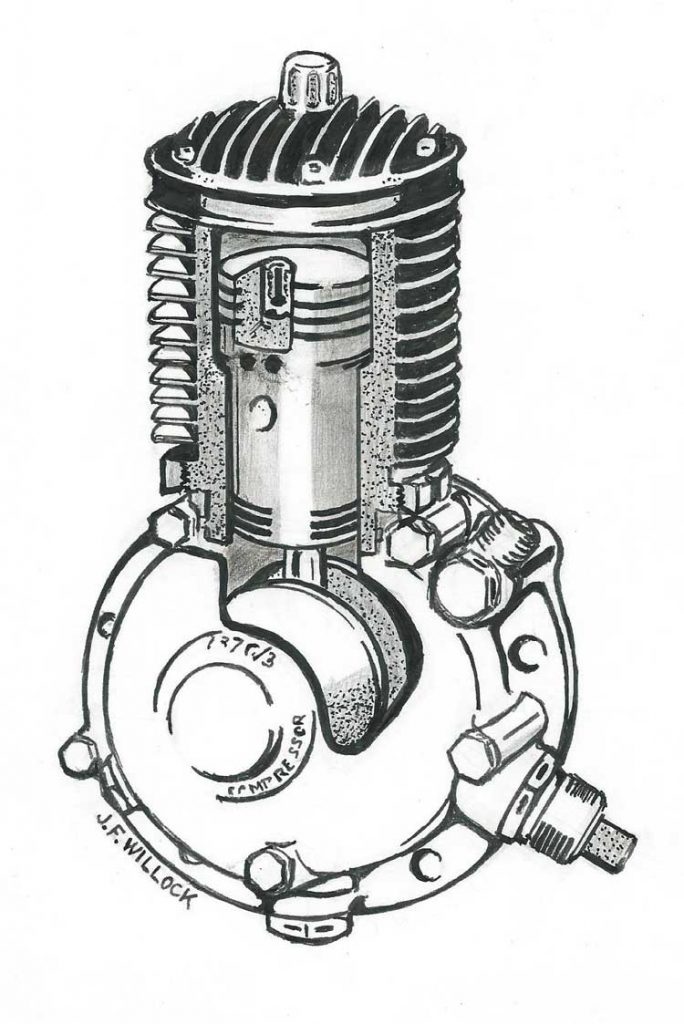
Left – The Heywood SH6 Series Air Compressor
As indicated, the Heywood compressor was installed in three of the most important British wartime aircraft; viz; the Supermarine Spitfire/Seafire, the Avro Lancaster and the de Havilland Mosquito. These three different types of aircraft all used a common engine, the Rolls-Royce Merlin, albeit it in numerous different versions. However, the installation of the compressor was similar whatever the version of Merlin engine.
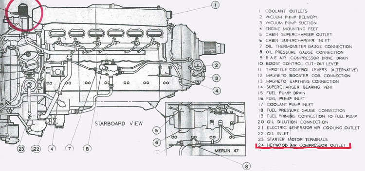
At the rear of each Merlin engine, usually on the Starboard side bank of cylinders, was a mounting interface where the Heywood compressor was located. The drive to the compressor was supplied by the Starboard camshaft, the actual connection being made via a splined coupling. As the Merlin was a conventional four-stroke internal combustion engine working on the Otto Cycle, the camshaft operating the valves revolved at exactly half the engine’s crankshaft revolutions. Thus the Heywood compressor always ran at camshaft speed – half the engine speed.
As the compressor was an integral part of the Rolls-Royce Merlin, it shared the engine’s lubrication system. Filtered engine oil entered the compressor under a pressure of between 30-75 lbs/sq inch, lubricating the generously proportioned main journal and crankpin bearings. The ball race supporting the crankshaft was lubricated by oil mist. With every revolution of the compressor’s crankshaft main journals, a squirt of oil was dispensed into the cylinder bore. All this ensured that the compressor was adequately lubricated. Further filtering of the oil took place as it passed back into the engine’s main lubrication system.
The Heywood compressor could charge a 400 cu. inch cylinder to 300 lbs/sq. inch in 4 minutes at 1,200 revs/minute or to 450 lbs/sq. inch in 6 minutes 15 seconds. The output was between 1-2 cu. ft. minute. Normal operating speed was 1,200 – 1,600 revs/minute. A speed of 2,200 revs/ minute could be sustained for a short period. This would equate to an engine crankshaft speed of 4,400 revs /minute, well beyond the sustainable operating speed of the Rolls-Royce Merlin.
On the Spitfire the Heywood unit provided compressed air to operate the wheel brakes, cock the eight Browning 0.303”machine guns and pneumatically function the wing flaps. In the case of the Lancaster two Heywood compressors, one situated on each of the two inner engines, supplied compressed air to operate the wheel brakes and radiator flaps. A single Heywood unit fitted to the Port engine of the Mosquito supplied compressed air to operate the wheel brakes, cock the guns, electro-pneumatically function the radiator flaps, engage the supercharger auto gear change controls and finally operate the carburettor filters.
The above aircraft were built in significant numbers; over 22,000 Spitfires/Seafires; nearly 7,400 Lancasters and approximately 7,800 Mosquito’s. To meet these requirements it would have been necessary to produce nearly 45,000 Heywood compressors. Not all these were made by the Heywood Company. It is possible that Enots Limited of Birmingham manufactured them too. The Bendix Corporation, and possibly other organisations in the United States, produced them in large numbers. The majority of these units would have been fitted to the Packard/Rolls-Royce Merlins built under licence in Detroit. These engines were subsequently shipped to Britain mainly for Lancaster production. A high proportion of Lancaster aircraft had Packard/Merlins. The Packard Corporation’s contribution to Merlin production was huge, with over 55,000 engines manufactured in the United States. It should be noted that the Packard/Merlin engine was also used in later versions of the North American P 51 Mustang, transforming the aircraft’s previously mediocre performance into the best all-round piston engined fighter of WWII.
As an aside, RAF ground crews and servicing personnel rather liked receiving the Packard-built Rolls-Royce Merlin engines, as they were usually supplied with superior kits of tools and equipment. It probably did not take too long for the sets of “Blue Point”/ “Snap On” wrenches and sockets to disappear without trace! Undoubtedly they were more highly prized than the distinctly “War Finish” British equivalents!
The reader has possibly discerned that no reference has been made to the Hawker Hurricane, another major British aircraft and the Spitfire’s more numerous Battle of Britain companion. The Hurricane was also equipped with an engine-driven air compressor, but perhaps unfortunately not the Heywood type. It was fitted with the BT-H A.V. Type of compressor; a somewhat smaller unit with an overall performance rather lower than that of the Heywood. As with the Spitfire, the A.V. Type supplied compressed air to the Hurricane’s wheel brakes and also cocked the eight or twelve 0.303” machine guns.
Under wartime conditions the imperative was to get fighter aircraft off the ground and into the air very quickly, and perhaps the deficiencies of the A.V. Type of compressor were then less apparent. However, excessive use of the brakes on the ground, as in taxiing, tended to run the little compressor “out of puff”. Recent restorations of Hurricane aircraft (R 4118 for example), that now taxi perhaps rather more, have tended to lead to the substitution of the BT-H A.V. Type compressor for a Heywood unit. The purists may probably grimace at this, but safety on aircraft tops everything! Why on earth the Air Ministry, in wartime, opted to have at least two different types of compressor in production simultaneously, with all the attendant difficulties of multiplication of spares, stock control, etc, etc, is beyond the author of this paper! The Hurricane could have been fairly easily adapted to receive the demonstrably superior Heywood compressor, and would have benefited significantly from the modification.
Construction:
The construction of the Heywood SH6/2 compressor was fairly straightforward and comprised a deeply finned steel cylinder with stepped diameter bores. On the outside diameter at its lower end, the cylinder carried two shouldered flanges, the upper one being larger and threaded. A delivery valve was positioned in the side wall of the cylinder near the base of the finning. Into the cylinder a stepped diameter (possibly aluminium) piston carrying six piston rings (three at the crown and three at the skirt) was fitted. The crown of the piston carried a spring loaded transfer valve with two communicating drilled holes exiting below the piston step. A solid steel gudgeon pin, secured to the piston by two grub screws, supported the connecting rod small end. At the lower end of the connecting rod a strapped and bolted bearing joint with split bushes was fitted. The crankshaft, probably an upset steel forging, comprised a crankpin between two disc type webs, a large plain bearing with integral internal spline and a small nose portion to receive a ball race. A number of suitably drilled holes in the crankshaft and crankpin permitted lubricating oil to reach all the journal bearing surfaces.
Comprising two light alloy die castings, the crankcase was split vertically and secured together by five equally spaced bolts. The rear portion of the crankcase carried a large phosphor bronze bearing bush to receive the crankshaft journal; a flanged and spigotted mounting face with six fixing holes provided the interface with the Rolls-Royce Merlin engine. The front portion of the crankcase contained a ball race which provided the outer crankshaft support. Both front and rear portions of the crankcase were integrally machined and featured shoulders, chamfers and undercuts to accurately receive and secure the cylinder. A banjo connection and threaded unions were located in the crankcase for respectively, ingress, egress and drainage of the lubricating oil. The castellated threaded locking ring had a tapered shoulder that matched a similar arrangement on the crankcase, and this ensured that the cylinder and crankcase elements were pulled together tightly. A tabbed locking strip engaged in one of the castellations of the locking ring to prevent unwanted rotation.
The deeply finned light alloy cylinder head, containing a centrally positioned filter/inlet valve, was secured to the cylinder with five cap head screws; the joint faces being made gas tight by a lead sealing ring. All bolts, pipe unions, etc. on the compressor were wire-locked in accordance with standard British aircraft practice.
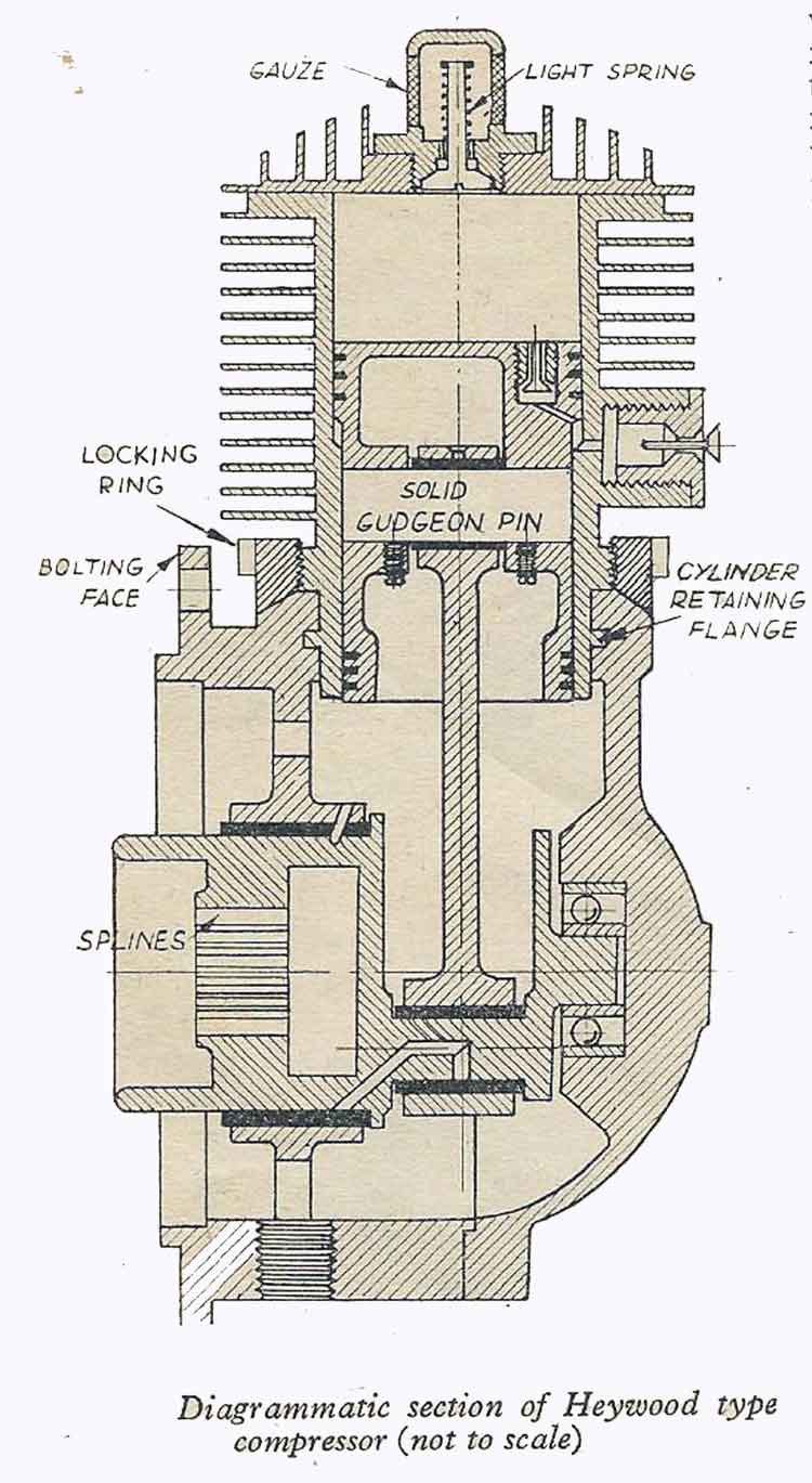
Operating Sequence – Please Refer to Diagram

Induction Stage:
With the piston at the top of it stroke and about to descend, filtered air from the atmosphere is drawn into the cylinder via the weakly spring loaded inlet valve A.
Compression Stage 1:
As the piston starts to ascend the weakly spring loaded inlet valve A closes and the resultant compression in the cylinder forces air past the transfer valve B, situated in the piston crown, into the annular space D between the reduced diameter of the piston and the larger bore of the cylinder. Since the swept volume of the cylinder is greater than the annular volume below the piston, the air can be said to be in the first stage of compression.
Compression Stage 2:
The second stage of compression takes place as the piston descends and forces air from the reducing annular volume D through the delivery valve C and thence to the receiver. Whilst this is happening air from the atmosphere is being drawn into the cylinder via the inlet valve A above the piston to enable the cycle of operations to be repeated.
After the war huge quantities of military surplus material came onto the open market. The Heywood compressor was no exception. An advert by the “Instrument Co” appeared in a 1949 edition of the Model Engineer offering brand new, American made, boxed Heywood Compressors for 29/6, plus 1/6 post. This sounds very cheap, but probably equates to £80-£90 in today’s currency. Undoubtedly many were purchased for commercial purposes or domestic and home workshop use. The main modification required to the compressor probably entailed reducing the output pressure, making it into a single stage unit. Driven by a fractional horsepower electric motor and allied to a suitable receiver, they would have been ideal for paint spraying or other workshop duties.
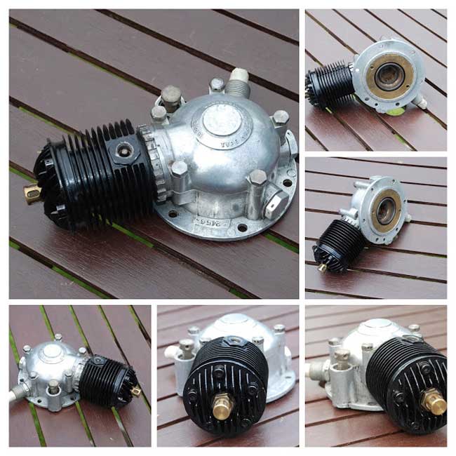
Heywood compressors can still be fairly readily found on e-bay, although much less frequently seen on car-boot markets. Some years ago, at a Steam Engine Rally in Shropshire, the writer saw a whole table full of them – possibly as many as twenty or so. All appeared to be in fairly pristine condition and were of US (Bendix) manufacture. They certainly looked as though they had never been used and probably had been in some RAF store for many years! The waste of war!
The Heywood compressor was a small, but absolutely essential ancillary unit, being fitted to at least three of Britain’s most important and successful wartime aircraft. It would be true to to say that none of these aircraft could have performed their respective duties without it. It was indeed a Worcestershire Wizard!
The author is indebted to Michael Doody for his kind assistance in the preparation of this paper. As always, the webmaster used his considerable IT skills to make this WIAS paper possible.
Thanks to them both.
References:
- The Model Engineer, Vol. 101, No 2529, Nov.10, 1949 & Vol. 102, No 2561, June 22, 1950
- Hurricane R 4118, Peter Vacher, Grub Street, London, 2005
- Avro Lancaster, Owners’ Workshop Manual, Haynes Publishing, 2008
- Rolls-Royce Merlin 45-55M Manual, Air Ministry Publication, 1944
- World Encyclopaedia of Aero Engines, Bill Gunston, Book Club Associates in conjunction with Patrick Stephens,1986
- WIAS Newsletter, February2020. Presentation given by the author on the Heywood Compressor.
Copyright © J F Willock June 2021
ADDENDUM
Additional information on ‘A Worcestershire Wizard’
Since the preparation and publication of this paper on the WIAS website, a certain amount of additional information emanating from original Heywood sources has been made available to the author. From this additional information it has become clear that a number of statements made in the original text are incorrect. It is the authors intention to attempt to correct these errors and also to expand on the early history of the Heywood Company. This additional information is largely contained in a memorandum written in July 1945 by Mr Joseph A. Hunt MBE (later Sir Joseph Hunt), a towering figure in the Heywood story, both during the war years and subsequently. Sir Joseph later became Pro-Chancellor of Aston University, Birmingham.
The business was formed as the Heywood Air Starter Company in October 1937- with a staff of one – Mr Joseph Hunt! The initial product was an air/petrol starter intended for high powered aero engines. It was not a success on most contemporary aero engines and was soon dropped. However, it was realised that with the rearmament programme gathering pace, there was a possible requirement for an aircraft air compressor. Thus in June 1938 work began, in concert with Heywood’s co-licensees in Switzerland (not France), to design and develop a compressor suitable for aircraft use. The key figure in Switzerland seems to have been a Monsieur Albert Moreillon.
A preliminary model compressor was offered to the Air Ministry (AM) for evaluation in the autumn of 1938. In March 1939 the AM recognising the need to modernise its aircraft compressed air systems, pressed for the development of the Heywood unit to be hastened. It was followed by a long period of development resulting in the unit being adopted for British operational aircraft. The compressor passed its100-hour Type Tests on both the Rolls-Royce Merlin and Bristol Perseus engines in June 1939. As it transpired the Perseus 9 cylinder radial sleeve-valve engine saw only limited military use. At the time there was only one sample compressor available. It was, therefore, not without considerable risk that these demanding tests were conducted on two very different types of aero engine using just one sample compressor!
Other projects being considered by Heywood had to be dropped in furtherance of the priority allocated to compressors. On 3rd September 1939, the AM telephoned Heywood to advise that the company’s air systems had been officially adopted and 4000 sets of equipment (compressors and pressure regulating valves) were urgently required! At the time the company comprised just five people including the office boy! The company had no manufacturing assets or test facilities and relied on sub-contractors for the manufacture of components.
Therefore, the first 1000 compressors were ordered from Switzerland in November 1939, to be followed by the balance being produced by the company using its own resources. Weeks of delay and vacillation followed and it was not until February1940 that authorisation was granted by the AM to proceed with British manufacture. A production facility was to be established at Redditch, and thus began a scramble to secure machine tools, materials and labour.
Half the machine tools ordered were lost; including those that could not be got out of Switzerland and Sweden, and others overtaken by events in the fall of Belgium and France. American made machines succumbed during Atlantic crossings. Special flights were also mounted by the RAF to get vital compressor components out of France before its occupation. Later, Swiss manufactured compressor (components?) were seemingly conveyed overland to Portugal, and thence by sea to the UK.
The Ministry of Aircraft Production (MAP) also placed contracts with Rotol Airscrews Ltd. and BT-H for compressor components. As an aside, the Rotol company came into being on May 13th 1937 and was set up jointly by Rolls-Royce Limited and the Bristol Aeroplane Company to manufacture constant-speed propellers, capable of being universally fitted on engines from either manufacturer. The Rotol factory was based at Staverton in Gloucestershire.
By Aug 1940 the Redditch factory was operational with a staff of 10 people. In December 1940 a bomb dropped within a few yards of the factory; very fortunately only two men were injured. The factory sustained only superficial damage, mostly from broken windows. At the end of December 1940 the company manufactured its first compressor.
January 1941 saw the completion of 1000 compressors assembled from Swiss parts. These went immediately into RAF service, together with Heywood automatic control valves made under sub-contract by M.C.L. Towards the end of 1941 the Redditch factory, which had been originally scheduled to make 160 compressors /month, was actually achieving with double shifts and overtime, 300/ units per month. On the other side of the Atlantic, the Packard Company in Detroit had produced its first licence built Merlin in 1941.
Heywood’s Chief Designer, at the request of the MAP, was sent to the United States to advise American manufacturers on the production of the company’s equipment. Undoubtedly his visit included discussions with engineers of the Bendix Corporation, as well as other organisations.
By December 1942 production had steadily risen to 850 compressors per month and the workforce was 198 people.
The year 1943 saw compressor production rise again to 1200 units / month.
In 1944, with the output of compressors reaching 1700 units/month, the manufacturing side of the business was moved out of Glover Street into more spacious premises. However, the Glover Street factory was retained as the company’s administration headquarters. It also continued to house the design function and a greatly enlarged experimental department.
Our story of the Heywood compressor ends in 1945. Considerable contraction took place and the manufacture of Heywood equipment in the USA and at the BT-H at Rugby ceased. Final production figures indicate that 2000 compressors / month were being manufactured, plus approximately1000 repaired units.
Company figures show that up to 1945, wartime production of aircraft compressors from all sources (Heywood, other UK companies and US manufacturers, but excluding Canada for which no figures were available) totalled 116,000 units. Similarly, 159,000 Automatic Regulator Valves and 74,000 Oil and Water Traps were also supplied. There is no evidence to indicate that Enots of Birmingham manufactured Heywood compressors.
No mention has been made in the foregoing account of the Heywood Company’s wartime contribution of compressed air equipment for British tanks, particularly the Cruiser, and also for marine applications. It is yet another part of the largely untold Heywood story!
The author is indebted to Stuart Lamb for making available this invaluable source of information on the Heywood compressor narrative, thus enabling several errors of commission and omission to be corrected.
Copyright © J F Willock June 2021