The Bentley BR1 & BR2 Rotary Aero Engines of World War 1
This paper is a brief history of the Bentley BR1 & BR2 Rotary Aero Engines of World War 1. These particular engines, designed by WO Bentley whilst he was seconded to the Humber Company at Coventry, were by common consent the best of all the rotary engines used in that conflict. Also included in this paper are other rotary engines that preceded the Bentley.
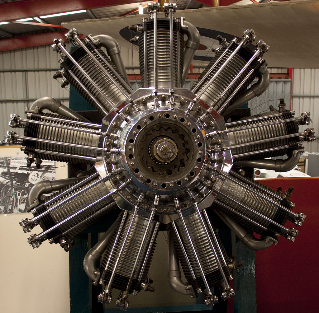
Tony Hisgett from Birmingham, UK, CC BY 2.0 https://creativecommons.org/licenses/by/2.0, via Wikimedia Commons
All the rotary engines mentioned in this paper operated on the four-stroke Otto cycle, viz, Induction, Compression, Ignition and Exhaust. However, the manner in which they precisely achieved the cycle of events varied considerably from engine to engine, particularly with regard to the induction stroke. The fact that the whole engine rotated had no relevance on the fundamental cycle of operation. The vast majority of the French and British rotaries were manufactured under wartime conditions, but despite this they were all extremely well made using first rate materials.
The rotary aero engine, initially in the form of the French manufactured Gnome of the early twentieth century, was a phenomenon which broke upon the embryonic aviation scene in 1908. Coming seemingly from nowhere, the rotary engine held uncontested sway for just about a decade and was then relegated, almost as quickly, to relative obscurity and obsolescence.
The idea of an internal combustion engine rotating about its own fixed crankshaft axis was not exactly new in 1908. At the Paris Universal Exposition of 1889, Felix-Theodore Millet (1844-1929) exhibited a patented five cylinder rotary engine built into a cycle wheel. Millet’s rotary powered wheel was taken up commercially by the Darracq Company in 1900, and they enjoyed a limited amount of success manufacturing and marketing this invention. Although there are a few other possible claimants, it does appear that Felix Millet may genuinely have originated the rotary engine concept.
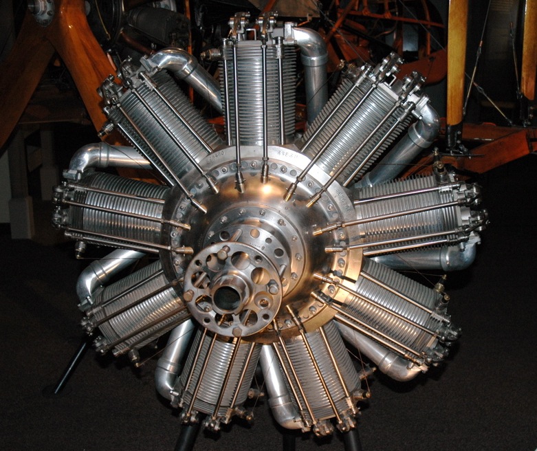
Early water cooled aero engines were developed from their automobile equivalents but they tended to be heavy and their power to weight ratio was relatively poor. Although light in weight, air cooled engines were unreliable and prone to seizing due to unequal thermal expansion in their cylinders. Into this arena came the 7 cylinder Gnome 50 h.p. Omega rotary engine, which was first exhibited at the Paris Automobile Show of 1908.
Societe Des Moteurs Gnome of 49 Rue Laffitte, Paris, was formed by Louis Seguin in 1906 to initially manufacture stationary industrial engines. When Laurent, the younger brother of Louis, joined the company they set out to design and manufacture a lightweight rotary aero engine. Undoubtedly the Seguin brothers had seen or heard about Millet’s rotary engine and perhaps believing that cylinder cooling would be significantly improved by having the entire engine rotate, they embarked upon the design of the Gnome.
At about this time nickel-chrome alloy steels were becoming available, with tensile strengths of 50/60 tons/sq.in (UTS). These are roughly equivalent to present day high tensile steels. The Seguin brothers took the opportunity to incorporate these alloy steels into their new engine. The cylinder wall thickness of all rotaries was very thin, in the region of only 1.5 mm (0.060”) in the Gnome, and nickel-chrome steels provided more than sufficient tensile strength to cope with the combined loads imposed by combustion pressures and centrifugal forces acting upon the rotating cylinders. The Gnome engine did not utilise shrunk-in cast iron cylinder liners, although most subsequent rotaries did, thus endowing them with improved working surfaces for their pistons.
Cylinders of the Gnome and subsequent rotary engines were machined from solid billets of nickel-chrome or equivalent steels (Holtzer ND). In the case of the Gnome each cylinder started off as a 67lb billet; this being reduced to about 5lbs after 3 hours of machining time on a suitably tooled Turret Lathe. The cooling fins were also machined at the same set up using special form tools. A period photograph of this particular cylinder machining operation looks suspiciously like it is being performed on a Herbert Turret Lathe.
All rotaries employed a hollow crankshaft, again made from a nickel-chrome alloy steel forging, through which the fuel/air mixture was admitted into the crankcase. A rudimentary “carburettor positioned at the rear of the crankshaft supplied the mixture. From the crankcase the fuel/air mixture was directed to the cylinders. In the case of the Gnome a weakly spring loaded automatic poppet valve centrally located in each piston crown permitted the fuel/air mixture to pass from the crankcase into the cylinder combustion chambers on the induction stroke. The poppet valve automatically closed as the individual pistons ascended on their compression stroke. The poppet valves demanded a high degree of attention, very careful setting and were not without their problems! There was of course always an explosive mixture below the pistons!
A new version of the Gnome Rotary, introduced in 1913 and called the Monosoupape (Single Valve) or alternatively the “Mono,” utilised a single pushrod operated dual- function inlet/exhaust valve in each cylinder head. Additionally, each cylinder liner of the “Mono” had at its lower extremity a series of drilled holes or ports that corresponded with transfer passages formed in the crankcase itself. Unlike all other rotaries the “Mono” had no carburettor as such, and very rich fuel was conveyed via the hollow crankshaft into the crankcase by an engine-driven pump. Engine speed governed the pump delivery rate. A little air was introduced into the crankcase, but not sufficient to form an explosive mixture. In operation, with the single inlet/exhaust valve open and the piston descending on the induction stroke, air was drawn into the cylinder. At or near the bottom of the induction stroke the inlet valve closed. Simultaneously the piston itself uncovered the drilled ports and transfer passages, allowing the rich fuel/air mix in the crankcase to be admitted into the cylinder. An explosive mixture was then formed with the supplementary inducted air. The piston then ascended compressing the fuel/air mixture contained within the cylinder. The power stroke then took place with the piston subsequently descending. At or near the bottom of the stroke the inlet/exhaust valve opened permitting the spent exhaust gasses to be swept from the cylinder by the ascending piston. The cycle was then repeated. The Monosupape operated on the four-stroke cycle although it was a much modified version. Due to its relative mechanical simplicity, the “Mono” had one of the best power to weight ratios of all the First World War rotary engines. All other rotary engines, viz. Le Rhone, Clerget, Siemens-Halske and the Bentley BR1 & BR2 utilised external transfer pipes, one per cylinder, to allow the fuel/air mixture to pass from the crankcase to the respective combustion chambers of each cylinder. Pushrod operated inlet valves, suitably timed off a cam ring, then admitted the fuel/air mixture into the respective cylinders.
Two other Paris based companies, already briefly mentioned, manufactured rotary aero engines and thus competed actively against the Gnome on the aviation scene. They were respectively Clerget-Blin & Cie established in 1911 at 37 Rue Cave, Levallois-Perret, a suburb to the north west of Paris noted for its industrial workshops, and the Le Rhone company founded in 1912 at 3 Rue La Boetie. In 1914 Le Rhone was taken over by the Gnome company and thus became Societe Des Moteurs Gnome et Rhone, although each part of the organisation retained its own identity and range of engines.
Clerget rotaries were fairly orthodox in their valve operation, with separate pushrods and rockers for inlet and exhaust valves. This permitted valve timing overlap. In keeping with the Gnome and Bentley engines the Clerget crankshaft and big end assembly employed conventional master and articulated connecting rods. In contrast the Le Rhone used only a single push-pull rod to operate both the inlet and exhaust valves off a single rocker, and whilst this was a clever arrangement it did not permit any valve overlap. Additionally, the Le Rhone big end and connecting rod assemblies were very unusual indeed. The connecting rods had slipper ends which were captively held in a bronze thrust block comprising three concentric circular tracks – three equispaced rods in the outer track, three equispaced rods in the middle track and the remaining three in the inner track. It did of course mean that the nine connecting rods were made in three different lengths. This arrangement was claimed to give a smoother running engine as it obviated unbalance from unequal piston acceleration between cylinders.
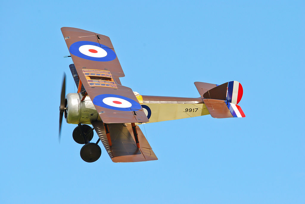
All these engines, Gnome, Gnome “Mono”, Le Rhone and Clerget were extensively used in numerous types of allied First World War aircraft. The Sopwith Pup, for example, used the 80 h.p. Le Rhone C engine and the Sopwith Camel a number of different versions of the Clerget. Gnomes were generally reserved for training or non front line aircraft, although the Gnome “Mono” was used in many French and British combat machines. Each type had their adherents. Royal Flying Corps engine fitters rather liked the Clerget and recorded the fact in their logbooks. Some pilots preferred the smooth running of the Le Rhone and said so. “Mine’s a peach. It’s a genuine Le Rhone Le Rhone”. Others commented more generally. “The French are damn good at making engines……”.
It would be wrong to infer from the above that French designed rotaries were exclusively manufactured in France. Licensed manufacture of all three major rotary engines was undertaken in Great Britain during the First World War. Peter Hooker of Walthamstow held a licence for the manufacture of the Gnome, W.H. Allen of Bedford for the Le Rhone and Gwynnes of Hammersmith for Clerget. Additionally, a good deal of sub-contracting must also have taken place. Documents in the Warwickshire County Record Office confirm that Willans and Robinson at Rugby manufactured large quantities of Le Rhone components for W.H. Allen of Bedford. It would appear that the Daimler Company manufactured the Gnome “Mono”, Le Rhone and subsequently the Bentley BR1 and BR2 engines. Whether they were “officially licensed” to manufacture French engines is debatable as they seemingly “reverse engineered” the “Mono” from a sample engine supplied – not from drawings. Hardly a normal situation for licensed manufacture!
It has been suggested by FR (Rod) Banks in his autobiography, I Kept No Diary, that Peter Hooker Ltd., also known as The British Gnome and Le Rhone Engine Co., made the best and most reliable examples of the French designed rotary engines. The company was renowned for a number of precision made products, most notably the supply of special colour printing presses for the printing trade. They applied their engineering prowess to the manufacture of rotary aero engines. Their licence built Gnome engines achieved 80 hours between overhauls against 15-25 hours for the French built equivalents. This was in no small part due to the special tools they designed and manufactured for the rolling of bronze “L” section piston obturator rings – fitted to all French designed rotaries – of which more later in this paper.
Peter Hooker Ltd. also developed a process for forging aluminium alloy (Y Alloy) pistons and cylinder heads for aero engines. Alloy pistons of this material were used in the Gnome Monosoupape engine and replaced those made of cast iron, its superior thermal conductivity made it ideal for this application. “Y” Alloy had been developed by the National Physical Laboratory and its composition was; 4% Copper, 2 % Nickel, 1.5% Magnesium and the balance aluminium. Rod Banks relates in his autobiography that strongly against his advice a one- off cylinder for a Gnome engine was manufactured in “Y” alloy. Prior to it being trialled in an actual engine, Banks warned that the test should be conducted in the open on a Gnome “gun carriage” type test stand, rather than in the normal enclosed “escargot” type test units, and everyone was to keep clear! The engine had barely completed a revolution and when the cylinder made of “Y “alloy actually fired it was propelled 70 feet into the air over the test house!
Walter Owen (“WO”) Bentley (1888 – 1971) was born at Hampstead, London, on 16th September 1888, into a comfortably well off family. He was the youngest of nine children. His father Alfred was a retired business man and his mother Emily (nee – Waterhouse), was of Australian birth. In due course he had the good fortune to be educated at Clifton College, Bristol. At the age of 16 “WO” commenced a 5 year premium apprenticeship with the Great Northern Railway Company (GNR) at Doncaster, where he was inculcated into the world of railway engineering. The GNR at this time was probably engaged in the construction of the second batch of its Atlantic express locomotives.
On the completion of his apprenticeship with the GNR in1910, “WO” decided that he did not want to continue his career in the railway industry and opted to study Theoretical Engineering at King’s College, London. At this time he also raced various makes of motor cycles and competed unsuccessfully in the Isle of Man Tourist Trophy races of 1909 and 1910.
In 1912 “WO” joined his brother Horace Millner Bentley as a business partner in the firm of Bentley and Bentley to sell the French made DFP (Doriot – Flandrin – Paran) car from premises in London. “WO” was disappointed with the performance of the DFP and thought their engines could be improved with the incorporation of aluminium alloy pistons, then still a comparative novelty; the conventional material being cast iron. This was done in 1913.
With the commencement of the First World War in 1914, “WO” volunteered for military service and was commissioned into the Royal Navy as a Technical Consultant. He was directed to Gywnnes of Hammersmith to oversee the manufacture of the Clerget 130 h.p. rotary aero engine being made under license by the firm. The Clerget was extensively used on the Western Front in many aircraft, including those used by the Royal Naval Air Service (RNAS). In addition to his work at Gywnnes “WO” was officially authorised to acquaint other firms, such as Rolls-Royce, with his own findings on aluminium pistons in DFP cars and the advantages that could be expected from their use. This was invaluable information which, if suitably disseminated, could aid the war effort considerably.
Unfortunately, although basically a fine piece of engineering, the Clerget suffered from a number of defects, including unequal cooling of its cylinders; steel not being a particularly good thermal conductor. Therefore, the cylinders were cool on their front leading edges, but very hot at the rear. This resulted in considerable asymmetric distortions in the cylinders, a problem not unique to the Clerget but experienced by all rotaries. In an attempt to mitigate these problems the Clerget used what was called a obturator ring, fitted at the top edge of each cast iron piston. The bronze obturator rings were of “L” section, very fragile with an operational life of only about 15 hours. To change the obturator rings necessitated a major engine strip down. Failure of an obturator ring in service usually resulted in piston seizure, followed by the total destruction of the engine. Bronze obturator rings were also used on the Gnome, Gnome “Mono” and Le Rhone engines, causing similar problems. On the Western Front there was consternation over the Clerget. “WO” visited France, perhaps on several occasions, to see the problems with the Clerget at the front.
Armed with this information “WO” attempted to implement a number of changes to the Clerget. These changes primarily focused on replacing the cast iron pistons with ones made from aluminium alloy. Pistons of this material had been previously tried in some Clerget engines with a noted improvement. However, Gwynnes were reluctant to implement this modification. Gwynnes position was perhaps understandable as they were not the design authority just licensees and Clerget in France retained close control of the design. “WO”and his navy superiors eventually became frustrated by the intransigence of Gwynnes and Clerget, and a decision was made to move “WO” to the Humber Company in Coventry with a view to designing a totally new engine.
This was new territory for “WO” who had never previously designed an engine, let alone an aero engine. With a small team at Humber he proceeded to conceive a new rotary, taking the best features of the Clerget and other engines, but incorporating new ideas that hopefully would obviate the problems of the past. Bentley retained the Clerget valve gear and cam ring assembly as he considered it was satisfactory, but completely altered the cylinder arrangement by substituting aluminium alloy L.8 cylinder barrels with shrunk in cast iron K.5 liners for the solid steel cylinders. An opportunity was also taken to incorporate detachable S.11 steel finned cylinder heads. Each cylinder barrel with its detachable head was secured to the crankcase by four long studs and castellated nuts and split pins; a method of construction that became the norm for many subsequent aero engines. The aluminium alloy L.8 pistons had slightly concave heads, each being fitted with five square section K.5 iron piston rings. Obturator rings were no longer used.

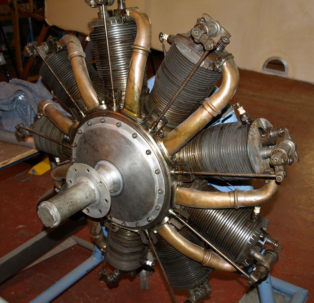
Nimbus227, Public domain, via Wikimedia Commons
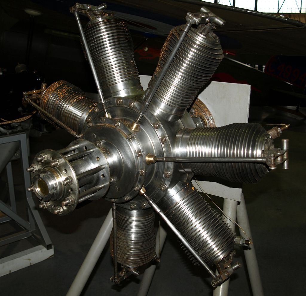
Nimbus227, Public domain, via Wikimedia Commons
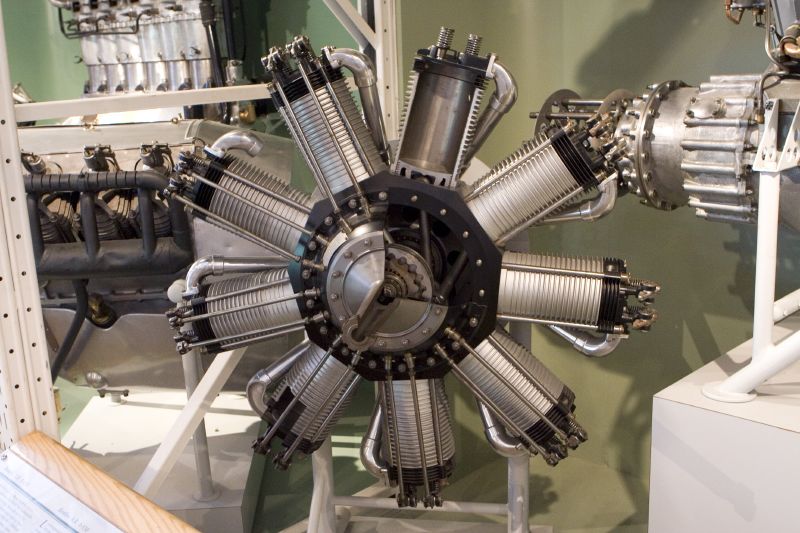
Nimbus227, Public domain, via Wikimedia Commons
lmnop88a, CC BY 2.0 https://creativecommons.org/licenses/by/2.0, via Wikimedia Commons
User:VargaA, CC BY-SA 4.0 https://creativecommons.org/licenses/by-sa/4.0, via Wikimedia Commons
Enjoy this Bentley BR1 Assembly Movie (HD) – Pierre Jansen
(For more engine assembly animations follow the link in blue above)

Enjoy this Bentley BR1 Assembly Movie (HD) – Pierre Jansen
(For more engine assembly animations follow the link in blue above)

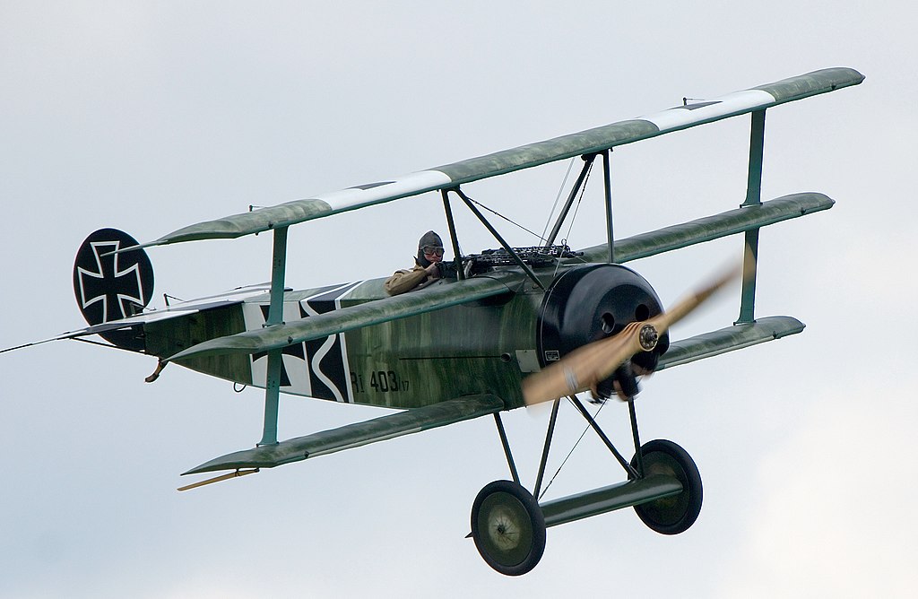
The largest known gathering of Fokker Dr.1 triplanes powered by original rotary engines since World War 1
The designation of the new rotary was originally intended to be the AR1, for Admiralty Rotary 1, but at the official transition of the Royal Flying Corps to the Royal Air Force in 1918, it was changed to BR1, for Bentley Rotary 1. This was probably in recognition of Bentley’s overall contribution. The BR1 had a swept volume of 1053 cu ins (17.3 litres) and delivered 158 h.p. for a dry weight of 408 lbs. This gave a weight to power ratio of 2.58 lbs/h.p. Whilst quite a respectable figure, it was not exactly outstanding amongst the rotary family of engines; the Gnome “Mono” 150 h.p. being demonstrably better at 2.08 lbs/h.p.
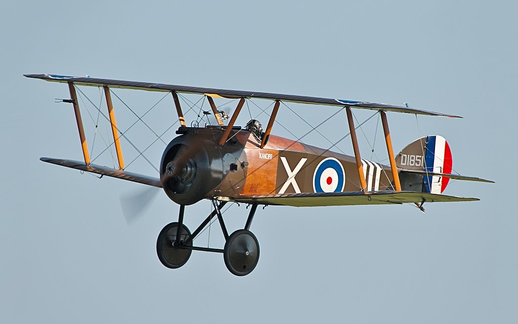
However, mere statistics were not the only criterion and do not convey the improved reliability and performance heralded by the introduction of the new Bentley BR1 on the Western Front. The BR1 was installed in the Sopwith Camel F1 and 2F-1, formerly mainly the preserve of the Clerget. In the hands of a competent pilot the BR1 engined Camel became a formidable weapon and deadly foe.
Buoyed by the success of the BR1, Bentley was authorised to design a slightly larger engine, the BR 2 of 1521 cu ins (24.9 litres) capacity, delivering 230 h.p. and destined to be the most powerful production rotary made. Whilst the weight of the BR2 had increased by 90 lbs over the BR1, its weight to power ratio improved considerably and was down to 2.165 lbs/h.p. The BR2 was installed in the Sopwith Snipe 7F-1, the ultimate rotary engined British fighter at the conclusion of World War1.
All rotary engines imparted considerable gyroscopic forces on the aeroplanes they powered. This often gave lightning quick responses, which were used to full effect in combat. The gyroscopic effect was probably most marked in the Sopwith Camel, a tricky aeroplane to fly for a novice pilot, but in the hands of seasoned veteran a deadly fighting machine that could outperform most German fighters. Unfortunately, the somewhat heavier BR1 &BR2 engines tended to make the Camel and its successor, the Sopwith Snipe, even more tricky to fly, perhaps slightly compensated by the greater power provided and improved reliability.
The Air Board were very impressed by the Bentley rotaries, particularly the BR 2, and ordered it into volume production in the Spring of 1918 at a targeted rate of 1500 engines per month. Humber alone did not have the resources to meet this requirement, and thus the Daimler Company was made the prime contractor with Humber and Crossley Motors of Gorton Manchester acting as subsidiaries. The BR2 came late in the First World War, but not too late to make a significant contribution towards overall allied air supremacy.
As is well known, WO Bentley went on to have a have a tremendously successful career in the British motor industry, forming Bentley Motors and in so doing producing some of the world’s most famous cars – but that is another story.
The reader may well be aware that no mention has been made of German rotary engines in this discourse. By and large German aircraft designers and engineers seemed to have favoured inline stationary aero engines, and developed them to a high degree, in preference to the rotary for their front-line aircraft. Nevertheless, Germany did use rotary engines to a limited extent, most noticeably the Oberursel and Thulin. Neither of these engines offered any new or original features of design. In fact the Oberursel was merely a clone of the French Le Rhone rotary, manufactured in a suburb of Frankfurt AM that supplied its name. The Thulin was a Swedish license built Le Rhone that found its way to Germany, probably illicitly. Perhaps the most noted application of the Oberursel was in the Fokker Dr.1 Triplane, used latterly by Manfred von Richthofen, the so called “Red Baron”, and the type of aircraft in which he was killed. German made rotaries suffered in comparison with their French and British counterparts, seemingly being less reliable and with a lower power output. This may have been due to inferior steels used in their construction and /or the use of lower quality lubricating oils. A captured Oberursel (Le Rhone copy) on test at Farnborough delivered 10% less power than its French built equivalent.
Germany did, however, produce one very original rotary engine during the First World War, this being the eleven cylinder Siemens and Halske Sh. III. This 18.6 litre engine, probably designed by CB Burdon or possibly Franz Dinslage, had the unusual feature of the cylinders, crankcase and propeller contra-rotating with the crankshaft, using a differential gear mechanism. Thus with the cylinders, crankcase and propeller rotating at 800 rpm in an anti-clockwise direction and the crankshaft rotating at 800 rpm in a clockwise direction the relative rotational speed of the cylinders, crankcase and propeller to the crankshaft was 1600 rpm. This was a somewhat higher rotational speed than conventional rotaries achieved and as a consequence permitted higher power outputs to be developed, with the additional benefit of considerably reduced centrifugal forces. The Sh. III was installed in the Siemens-Schuckert D III and D IV scouts. Endowed with an extremely good rate of climb, both these aircraft were probably the best German combat machines to reach operational status in World War1.
An important consideration for all rotary engines was lubrication. The absolutely preferred lubricant for rotary engines was castor oil, a vegetable based oil derived from the castor bean. Castor oil was and still is a superb lubricant, but lacking additives is not really suitable for modern engines, except possibly those used for racing purposes and likely to be stripped down very frequently. The problem with castor oil is that it has a propensity to rapidly gum-up and is temperature sensitive. However, in rotaries it was ideal. Because the rotary engine worked on a total loss lubrication system, a proportion of castor oil was ejected unburnt from the exhaust ports. Most rotaries were closely cowled in order to contain exhaust gases and expelled oil, which were then generally dissipated on the underside of the aircraft. There does seem to be something of a current debate as to whether the ejected castor oil had an adverse effect upon pilots, making them sick, or not, as the case may be. After much reading on the subject, the author is still uncertain as to whether castor oil sickness amongst pilots was a reality or has just become an urban myth. Castor oil may have affected some pilots, whereas others experienced no problems.
Due to the Royal Navy blockade of Germany in WW1, certain strategic materials were in short supply or denied completely to the enemy, including the availability of castor beans. This prevented Germany’s access to castor oil. As an alternative Germany sought to use other vegetable oil extracts, but these were mostly unsatisfactory in rotary engines. Mineral based oils could be used as a substitute, but castor oil was the lubricant of first choice.
The main problem with all rotaries was one of breathing. Put simply the rotary just ran out of “puff”. Out of necessity the route by which the fuel/air mixture arrived at the combustion chambers was long and tortuous in all rotaries, and in effect the cylinders were not filled completely and efficiently with explosive gas. This seriously limited their development potential and whereas the stationary aero engine continued to improve in all areas, the rotary stagnated. Brake Mean Effective Pressures (BMEP’s), the yardstick of internal combustion engine efficiency, were consistently lower in rotary aero engines than in inline types. It was clear that despite clever design and first class workmanship the rotary engine had reached the end of the line. By 1919 practically all development of the rotary aero engine had ceased and it was condemned to virtual obsolescence thereafter.
According to figures compiled from official documents in 1931, just over nineteen thousand rotary engines (presumably of French and British manufacture) were produced for use by British forces between the years 1914-18. In the same period, according to the same source, 8,246 British rotary engined scouts (fighters) were produced, presumably with both French and British manufactured engines. According to yet another source, not referenced, some 30,000 Bentley BR2 engines were ultimately produced. The author of this paper thinks this is a very high figure indeed for the BR2, it may be correct, but seems very unlikely.
The rotary aero engine burst on to the aviation scene like an unheralded comet in 1908; dazzled the world of flying spectacularly for a decade and then disappeared just as quickly, almost without trace. Its contribution during the early days of aviation and subsequently in the aerial fighting of the First World War was very significant indeed. Few rotary engines still exist except a handful exhibited in museums, notably in the United Kingdom at the Shuttleworth Trust at Biggleswade, Bedfordshire, where they are occasionally flown in aircraft. But not many of these are Bentley BR1s & BR2s – the best of all the rotaries, designed and made in Warwickshire!
John5199, CC BY 2.0 https://creativecommons.org/licenses/by/2.0, via Wikimedia Commons
Airwolfhound, CC BY-SA 2.0 https://creativecommons.org/licenses/by-sa/2.0, via Wikimedia Commons

John S. (Steve) Bond, CC BY-SA 4.0 https://creativecommons.org/licenses/by-sa/4.0, via Wikimedia Commons
User:MatthiasKabel, CC BY-SA 3.0 https://creativecommons.org/licenses/by-sa/3.0, via Wikimedia Commons
Postscript
In1981 a remarkable masterpiece of miniature engineering appeared that year at the Model Engineer Exhibition, held at Wembley, London. The model in question was a one quarter scale working reproduction of the Bentley BR2 rotary engine made by an Australian gentleman, Mr LK Blackmore. Prior to his retirement Mr Blackmore had never done any model engineering. Another almost unbelievable fact was the model was constructed without reference to any drawings – the only document available being a cross-sectional arrangement drawing that appeared in an official Air Ministry Handbook. No original Bentley BR2 drawings were found prior to the model’s construction and none have been found since. The model was awarded a Gold Medal at the 1981 Exhibition. As a Gold Medal winner, Mr Blackmore’s model was eligible as a contender for the Duke of Edinburgh Challenge Trophy. The model won this trophy at the 1982 Model Engineer Exhibition. Since the completion of Mr Blackmore’s model several other BR2 engines have been constructed. At least two of these have been awarded Model Engineer Exhibition Gold Medals.
The author would like to thank Alain Foote and the WIAS webmaster for their kind assistance in the preparation of this article.
Copyright © JF Willock January 2022
References:
- Aero Engines, GA Burls, Charles Griffin and Company Ltd., London, 1915
- Bentley BR2 World War 1 Rotary Aero Engine, LK Blackmore, Camden Miniature Steam Services, Frome, 2005
- The Rotary Aero Engine, Andrew Nahum, Science Museum, HMSO, London, 1987
- Fighters, Attack and Training Aircraft 1914-19, The Pocket Encyclopaedia of World Aircraft in Colour Series, Kenneth Munson, Blandford Press, London, 1968
- Rotary Engines of World War One, William Morse, Nelson and Saunders Aviation Collection, Olney 1987
- World Encyclopaedia of Aero Engines, Bill Gunston, Guild Publishing, London, 1986
- How to Lay-Out Turret Lathe Tools, Anonymous, Alfred Herbert Ltd, Coventry, 1917
- Willans and Robinson Archive, Ref. CR403I C7/51,CR 4031/6/208, Warwickshire County Record Office, Warwick
- I Kept No Diary, Air Commodore FR (Rod) Banks, Airlife Publications, Shrewsbury, 1978.
ADDENDUM
Additional information on ‘The Bentley BR1 & BR2 ’
Since the preparation and publication of this paper on the website, certain additional and corrective information has been made available to the author. This information has emanated from Dr. Tom Dine, Hon. Archivist of the WO Bentley Memorial Foundation Museum based, at Wroxton in Oxfordshire. Dr Dine is an authority on the Bentley BR1 & BR2 rotaries having published a major work on the subject in 2014.
Apparently Gwynnes of Chiswick, the licensees of the French Clerget rotary, did produce a number of sample engines incorporating modifications in accordance with WO Bentley’s recommendations. Designated the Clerget 9J, these engines bore a marked resemblance to the subsequent AR1/BR1 rotaries produced at Coventry by Humber. A rare surviving example of the Gwynne/Clerget 9J, one of only two in existence, is exhibited at the Museum of Lincolnshire Life at Lincoln.
Although Bentley had achieved much at Chiswick he was happy to make the move to Coventry, having previously formed friendships with a number of Humber personnel, during his participation in the 1914 TT races with his modified DFP car. Among these friends was FT Burgess who was to follow “WO” to Cricklewood and assist in the work on the first Bentley cars.
The AR1 and Bentley BR1 were identical designs, and the change of name to BR1 would appear to be in deference to the designer. It is thought that at least 120 AR1s were built, this figure being derived from the highest surviving engine number.
The first Bentley BR1 was manufactured by Humber Company in November 1916. This particular engine is exhibited at the Midland Air Museum, Coventry, and the makers plate is illustrated below. Humber produced 600 BR1s and Vickers a further 550. Humber was responsible for research, development and production of the BR1 and the Daimler Company became the production hub for the BR2. Subsequently 4900 BR2s were manufactured. At the cessation of the First World War contracts for the BR2 were curtailed or cancelled.

The Sopwith Snipe, fitted with the BR2, was in front line service from 1918 until made obsolete by the RAF in 1928. Other aircraft fitted with the BR2 included the Gloster Nightjar, Gloster Sparrowhawk, Parnell Panther and Grain Griffin; all these aircraft remained in service well into the 1920s. Many RAF trainee pilots in the inter-war years gained their “wings” on the rotary engined Avro 504K – although this particular machine mostly used French rotaries. A later version, the Avro 504L, was however designed to receive the BR1.
Although Mr Lew Blackmore was unable to find original Bentley BR2 drawings on which to base his fine quarter scale model, the author of this paper is assured by Dr. Dine that these documents do in fact exist.
WO Bentley’s name in popular imagination will always be associated with his famous motor cars, particularly those of the 1920s. However, “WO” recalled in later life that he considered the most satisfying time in his entire engineering career was spent at Chiswick and Coventry, designing the BR1 & BR2 Rotary Aero Engines of World War 1.
The author of this paper is particularly indebted to Dr Tom Dine and would like to thank him for correcting these errors of commission and omission.
JF Willock February 2022